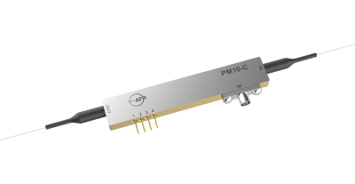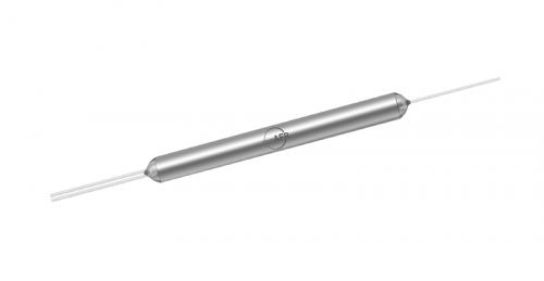
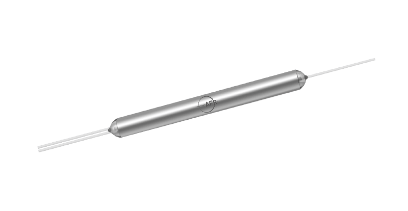
The Polarization Maintaining Fused Coupler offers very low insertion loss, high polarization extinction ratio and excellent environmental stability. Accurate coupling ratios from 0.01/99.99 to 50/50 are available with very good uniformity at center wavelength. These components find extensive applications to perform power splitting and mornitoring functions in all kinds of optical communication systems.
Product Detail
|
Key Features |
Applications |
|
Wavelength 488 - 2100 nm Available |
Power Monitoring |
|
Coupling Ratio from 0.01/99.99 to 50/50 Available |
Coherent Communication |
|
Operating on both Fast and Slow Axis |
Fiber Gyroscope |
|
Low Excess Loss |
Fiber Laser |
|
High Power Handling |
Fiber Amplifier |
|
High Stability and Reliability |
Test Equipment |
|
Specifications |
||||||||||||
|
Parameter |
Unit |
Value |
||||||||||
|
Center Wavelength (λc) |
nm |
488, 532, 635 |
780, 830 |
980, 1064 |
1310, 1480, 1550 |
1700, 2000 |
||||||
|
Operating Wavelength |
nm |
λc ± 5 |
λc ± 10 |
λc ± 10 |
λc ± 20 |
λc ± 20 |
||||||
|
Typ. Excess Loss |
dB |
0.8 |
0.5 |
0.4 |
0.2 |
0.5 |
||||||
|
Max. Excess Loss |
dB |
1.2 |
0.8 |
0.6 |
0.4 |
0.8 |
||||||
|
Min. ER1, 2, 3 |
dB |
18 |
18 |
20 |
20 |
20 |
||||||
|
Max. Excess Loss for each connector |
dB |
1.5 |
0.7 |
0.5 |
0.3 |
0.3 |
||||||
|
Max. Optical Power (Continuous Wave)4 |
W |
2 |
||||||||||
|
Thermal Stability |
dB/℃ |
|
|
|
|
≤ 0.005 |
|
|
|
|
||
|
Min. Return Loss5 |
dB |
50 |
||||||||||
|
Min. Directivity |
dB |
|
|
|
|
50 |
|
|
|
|
||
|
Fiber Type for Signal Port |
- |
PM Panda Fiber |
||||||||||
|
Fiber Type for Tap Port |
- |
|
|
|
|
PM Panda Fiber or Singlemode Fiber |
|
|
|
|
||
|
Operating Temperature |
℃ |
- 5 to + 70 |
||||||||||
|
Storage Temperature |
℃ |
|
|
|
|
- 40 to + 85 |
|
|
|
|
||
|
Coupling Ratio & Its Tolerance6 |
- |
|||||||||||
|
Coupling Ratio |
% |
1/99 |
2/98 |
5/95 |
10/90 |
20/80 |
30/70 |
40/60 |
50/50 |
|||
|
Max. Coupling Ratio Tolerance, λc |
% |
± 0.3 |
± 0.5 |
± 0.7 |
± 1.0 |
± 2.0 |
± 2.0 |
± 2.5 |
± 3.0 |
|||
|
Coupling Ratio |
% |
|
|
|
0.1/99.9 |
|
|
|
0.01/99.99 |
|
|
|
|
Tap Ratio Tolerance, λc |
dB |
30 ± 3 |
40 ± 4 |
|||||||||
1ER data listed in the table are for the ports with coupling ratio greater than 10%. It will be 2 dB lower for a tap port with coupling ratio between 1-10%. For 1% tap port, ER is not considered.
2ER will be 2 dB lower for Nufern FUD-3460 fiber and Nufern PM 1950.
3ER is 2 dB lower for each connector added. Connector key is aligned to slow axis.
4The Optical Power is 1 W only for connector added. For visible wavelength, the limit is 50 mW.
5RL is 5 dB lower for connector added.
6Data tested at central wavelength only.